mirror of
https://github.com/OSURoboticsClub/Rover_2017_2018.git
synced 2025-11-08 10:11:14 +00:00
2.1 KiB
2.1 KiB
IRIS Node
Designed by Nick McComb for OSURC Mars Rover.
Summary
Made for MR1718 as part of the OSU Robotics Club.
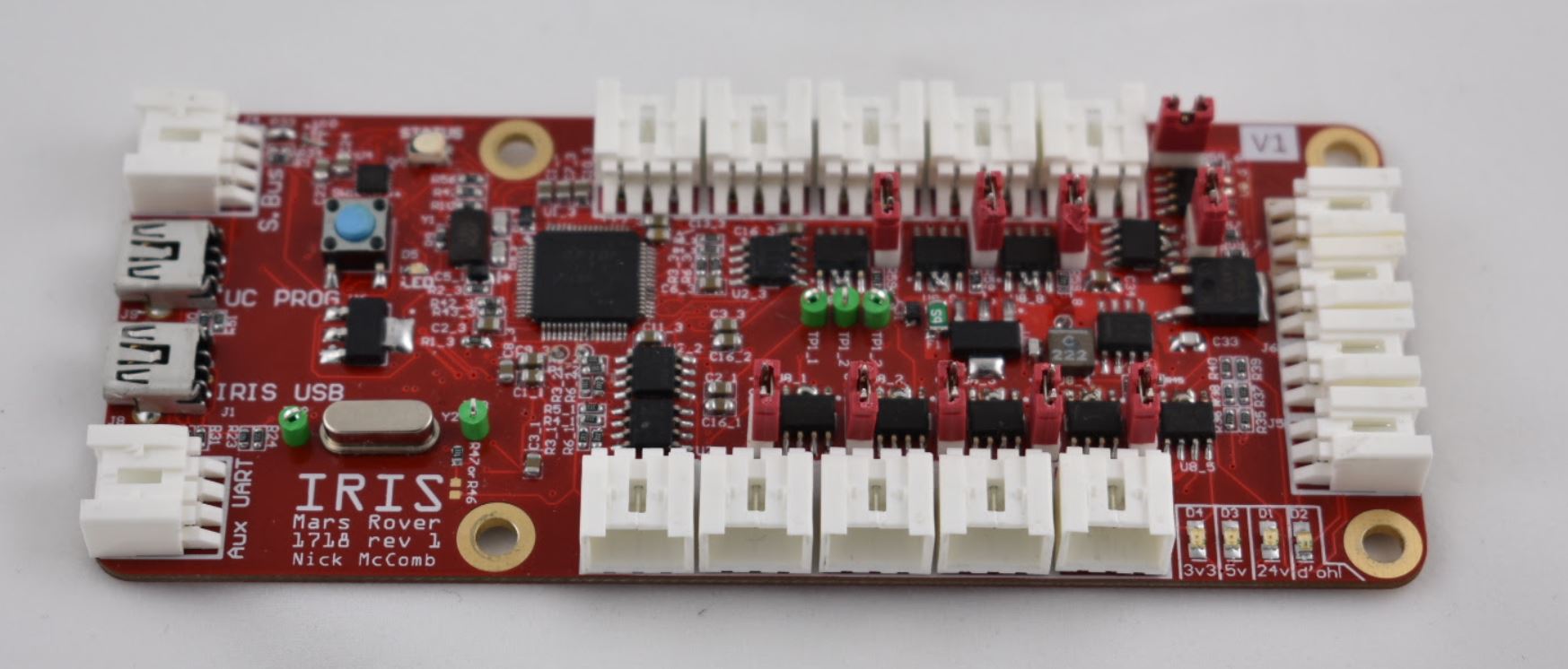
Enables a single USB port to act as 10 RS485 Transceivers, receive inputs from an S.BUS style RC receiver, and interface with a few switches. Input power is 24V (self powered, no power is drawn from the USB connection). Features a Teensy 3.2 microcontroller.
This design is entirely Open Source and is available on CircuitMaker, see below for a link to the file.
This is a 4-layer design.
The name "Iris" comes from the greek messenger god, Iris. This is the board that acts as a "messenger god" for our computer, telling the rest of the robot what to do.
Bill of Materials
Design files
Downloads
Known Issues
Version 1
- Used CAN tx/rx instead of hardware UART
- Connections from FTDI to RS485 transceiver wrong, need to short DE / RE pins together, then this connection goes to FTDI enable. PWREN for the RS485 converted is wrong naming and doesn’t reflect its purpose. No connection to PWREN on 4232 needed...
- Missing 3v3 rail connection to VBAT pin on Teensy. Will program without it, but will not boot without it.
- For R46 vs R47 selection, only R47 is needed.
- No invert needed for S.BUS connection (bridge pins)
- No serial number spot on silkscreen
- No MODBUS ID number spot on silkscreen
- Likely that this should use a high-speed USB hub instead of the current full-speed implementation. It is easy, without deliberate planning, to hit the bottleneck of the USB hub.
- Remove GND connection for RS485 going out of the board (to ensure reverse protection downstream)

